Friday, December 25, 2009

Woodbury Common Chanel Bags

Contador


This circuit was developed to use a keyboard, often found on the Internet only matrix keyboards can only handle with pic.

This keyboard is unique in using a pic which provides a binary combination of 8 bits, as an example place 10 buttons but can extend to many more all we need is to add more resistors in series, these resistors create a divider voltage to each other, that way we can make the fence ADC converting analog data to digital. Taking and the respective combination can connect a pic, digital gates or any other possible application.

Used Components:

- 1 ADC0804.
- 1 100nF Ceramic Capacitor.
- 1 Ceramic Capacitor 150pF.
- 8 Ohm Resistor 330R 1 / 2 Watt.
- 9 buttons.
- 11 Resistors 10K Ohm 1 / 2 Watt.

Sunday, December 20, 2009

Is Guides Gear Any Good

MC14553 ADC keyboard


This project is a 3-digit decimal counter unlike 74LS90 this circuit has the feature that automatically controls the display, indicating the reduction 3-decoders integrated circuits 74LS90 and 74LS47 BCD Binary-two integrated only a counter and a decoder.

The MC14553 integrated 74LS90 consists of counters, latches that store information for a specific period and controlling the display multiplexing. On pin 1 (C1B) and 3 (C1B), are those that control the internal oscillation to display the sweep of the display. Pin 14 (OVERFLOW) which allows wide range with another counter MC14553. Pin 13 (RESET) then obviously serves to reset the circuit. Pin 10 (LATCH ENABLE) functions as a stop it does is disable the latches to continue loading data and results stay with the previous digit. Pin 12 (Clock) is where we connect the frequency in this case provided by the LM555. Pin 11 (DISABLE) disables the clock. The maximum voltage is 18V.

Used Components:

- 1 MC14553 IC.
- 1 CI 74LS47.
- 1 LM555 IC.
- 1 10uF 16V electrolytic capacitor.
- 1 10nF Ceramic Capacitor.
- 1 Ceramic Capacitor 1nF.
- 1 10K ohm resistor 1 / 2 Watt.
- a 100K pot.
- 1K ohms resistors 2 1 / 2 watt.
- 2 330R resistors ohms 1 / 2 watt.
- Led 2.
- 2 100nF.
- 2 pushers.
- 3 Common anode display.
- 3 2N3906 transistors.
- 3 ohms resistor 100R 1 / 2 watt.

Tuesday, December 15, 2009

What Is Good Wall Color With Travertine


To conclude the subject of a Parallel and Serial two circuits each have their individual voltage source represent how data is transmitted is the ground wire and data would connect the two integrated circuits for lack of frequency cable also provided by the LM555 also share but in a real transmission each must have its own oscillator.

As I mentioned earlier in the integrated circuit can convert parallel data to serial form is 74LS165 and 74LS164 integrated circuit that performs the opposite process converts serial to parallel this way we can and make a digital transmission but would require a system that later it would give the encoding and decoding.

Used Components:


- 1 LM555 IC.
- 1 CI 74LS164.
- 1 CI 74LS165.
- 1 Dipswitch 8 Pin.
- 1 10uF 16V Electrolytic Capacitor.
- 1 10nF Ceramic Capacitor.
- 1 100K Ohm potentiometer.
- 1 10K ohm resistor 1 / 2 Watt.
- 1 CI 74LS374.
- 2 CMOS IC 4017.
- 2 CI 74LS04.
- 8 Ohm Resistor 220R 1 / 2 Watt.
- 13 Ohm Resistor 330R 1 / 2 Watt.
- 13 Led.

Thursday, December 10, 2009

Homemade African American Hair Relaxer

Conversion Total Conversion Conversion Palalelo Series Parallel Series


Complementing the Serial Parallel Converter Circuit, explained now the other party to convert the 8 bits in a Serial to parallel.

We have a LM555 which gives the frequency, we have attached a CMOS 4017 which gives us the account to load the data in a serial to parallel and after a buffer composed of 74LS374 type D flip flop which acts as a temporary memory, data is loaded serially into 74LS164 integrated on pins 1 and 2 are inputs to an AND gate but the output of this data does not come instantly, go through each output is necessary so memory data is loaded on one side and passing the changed 8 a section to be represented this is done in parallel in the buffer. The maximum voltage is 6V 74LS164 integrated, the maximum frequency is 25Mhz. The maximum voltage of 6V 74LS374 Integrated and frequency is 20MHz.

Components Used:

- 1 LM555 IC.
- 1 CI 74LS164.
- a CMOS IC 4017.
- 1 CI 74LS374.
- 1 CI 74LS04.
- a button.
- a 10uF 16V capacitor electrodeposition.
- 1 10nF Ceramic Capacitor.
- a pot 100K ohms.
- a resistance of 10K ohms 1 / 2 watt.
- Led 2.
- 3 ohms resistor 330R 1 / 2 watt.


Saturday, December 5, 2009

Many Calories Do Noodles Have


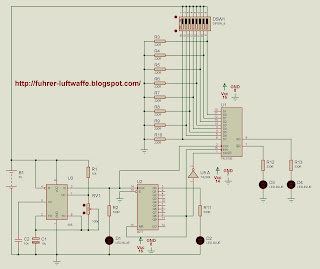
This circuit is very critical when we want to transmit digital data 8 bits in parallel and can convert them to serial form indicating that they will go successive 8 bits.

of 11 to 14 and 3 to 6 is where we connect the 8 bits and are the frequency 6V and for this we use the integrated circuit 74LS165 works asynchronously loads the parallel data when in low pin 1 which is PL (Parallel Load), the serial outputs are integrated pin 9 which is the normal output and the pin 7 output is denied, the patillaspatilla 11 is the least significativapatilla 6 is the most significant, to enter more data or expand the number of bits is necessary to place another integrated and its serial output is connected to the pin 10 DS (Serial Data), we also have a LM555 which gives us the frequency with which you enter the 8 bits to indicate the 74LS165 integrated that loads any data and emerging data have used the 4017 CMOS integrated circuit is a decimal counter. Máximomáxima voltage is 20MHz. Applications

as I mentioned we can use to transmit data serially entered in parallel as an example we could enter the 8-bit ADC to convert and transmit serial digital-mind.

Used Components:

- 1 CI 74LS165.
- 1 LM555 IC.
- 1 CMOS IC 4017.
- 1 CI 74LS04.
- 1 100K Ohm potentiometer.
- 1 10K ohm resistor 1 / 2 Watt.
- 1 Dipswitch 8 Pin.
- 1 10uF 16v electrolytic capacitor.
- 1 10nF Ceramic Capacitor.
- 4 Led.
- 4 Ohm Resistor 330R 1 / 2 Watt.
- 8 Ohm Resistor 220R 1 / 2 Watt.