Monday, November 30, 2009

What Colour Has Davina In Her Hair

Op-amp LM741 Oscillator


Wonder Continuing the LM741 Op-amp, a very interesting application, which is a configuration as an oscillator. Its operation is simple from an oscillation noise is created sustainable which is amplified by the op-amp has a potentiometer which varies the frequency together with the capacitor C1, as well as resistors R1 and R2 are the ones that control the duty cycle, if we put a potentiometer to replace these two resistances can get a variation of duty cycle, the capacitor C2 is simply placed to eliminate noise in the circuit, the LM741 voltage is 12V maximum.

Used Components.

- 1 Op-amp LM741.
- 1 100uF 100V Electrolytic Capacitor.
- 1 Ohm Potentiometer 1000K.
- 1 Capacitor 1uF 16V.
- 2 51K ohm resistors 1 / 2 Watt.
- 2 Ohm Resistor 330R 1 / 2 Watt.
- 2 LED's.
Wednesday, November 25, 2009

How To Make Simple Bubble Skirt

Bit ADC 2 CD4047 oscillator


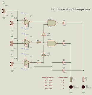
This is the operating principle of the ADC0804, the circuit operates with voltages of reference set by using op-amp, the main idea is that we can convert alternating voltage to a voltage then in various forms digital potentiometer with 0V to 5V can see different combinations represented with binary numbers. We use the LM741 with a configuration which provides a reference voltage potentiometers located with 50K, in which we can provide to make the switch voltage. The 100k potentiometer is the one going by the overall change from 0V to 5V, to work well the circuit need symmetric source of 12V and-12V.

Used Components:

- 1 100K Ohm potentiometer.
- 1 CI 74LS08 (AND).
- 1 CI74Ls04 (NOT).
- 2 Led
- 2 Ohm Resistor 330R 1 / 2 Watt.
- 3 Resistors 10K Ohm 1 / 2 Watt.
- 3 LM741 Op-Amp.
- 3 Potentiometers 50K Ohms.
- 4 1N4007 diodes.

Note: The diagram does not indicate it but the 74LS08 and 74LS04 integrated are connected to direct current, the pin 14 is Vcc = 5V, and pin 7 is GND or Ground.

Friday, November 20, 2009

Al Sharpton Case De Sushi Vid


CD4047 CMOS integrated circuit is astable oscillator which contains three frequency outputs, the main is located on pin 13 is the main frequency, the other two are outputs of flip-flop as a refusal and the other normal, these two frequency outputs are divisions of this means that the other outputs are equivalent to half the main frequency. The advantage of this oscillator is that its duty cycle is constant and can be varied with a potentiometer frequency, input voltage can be 15V max. With a maximum frequency of 10MHz.

Used Components:

- 1 CD4047 CMOS.
- 1 1uF 16V electrolytic capacitor.
- 1 10K ohm resistor 1 / 2 Watt.
- 1 Potentiometer 100K Ohms.
- 2 100uF capacitors. 100V.
- 3 Led.
- 3 Ohm Resistor 330R 1 / 2 Watt.

Sunday, November 15, 2009

How Long Can I Store Lsd


Another method of using the voltage is 120V AC using a triac optocoupler has the advantage of being more effective and eliminates the noise provided by the relay, triac BT136 is used to support a current of 3A, so we can demonstrate the great utility that provides a remote control. Used Components


- 1 Receiver 4021.
- 1 2N3906 Transistor.
- 1 Capacitor 10uF 16V.
- 1 220K Ohm resistor 1 / 2 Watt.
- 1 IC CD4017.
- 1 optocoupler MOC3021.
- 1 Triac BT136.
- 2 Led.
- 3 100nF Ceramic Capacitors.
- 4 Ohm Resistor 330R 1 / 2 Watt.

Tuesday, November 10, 2009

Antique Metal Bathtub

optocoupler Remote Control Remote Control Remote Control Relay


This circuit is an example of how we can use a remote control to turn on an appliance or just some electronics. In this case we use a 5V relay to power an incandescent bulb or thrifty, but the idea is that we can attach it depending on our needs.

Materials Used:

- 1 Receiver 4021.
- 1 CD4017 CMOS IC.
- 1 2N3906 Transistor.
- 1 2N3904 Transistor.
- 1 220K Ohm resistor 1 / 2 Watt.
- 1 10uF 16V Electrolytic Capacitor.
- 1 1K ohm resistor 1 / 2 Watt.
- 1 1N4007 diode.
- 1 5V relay.
- 2 Ohm Resistor 330R 1 / 2 Watt.
- 2 LEDs.
- 3 100nF Ceramic Capacitors.

Thursday, November 5, 2009

Used Taylor Yogurt Machine


This circuit is very necessary in our album have indispensable knowledge, acts in a very simple, with any remote control can trigger some kind of distance appliance or other electronic device.

The operation is very simple at the receiver which is a 38KHz signal demodulator. Enter the remote control signal is then amplified by the transistor, is then sent to a CMOS counter 4017, which alternated between two states only, in this example we put more than two LEDs, just to demonstrate the efficiency of the circuit, if all pulses sent by the remote control will be counted by the IC 4017 and thus turn certain LEDs.

Materials Used:

- 1 Receiver 4021.
- 1 2N3906 Transistor.
- 1 10uF 16V Electrolytic Capacitor.
- 1 220K Ohm resistor 1 / 2 Watt.
- 1 CD4017 CMOS integrated circuit.
- 3 100nF Ceramic Capacitors.
- 5 Ohm Resistor 330R 1 / 2 Watt.
- 5 LED's.