Friday, December 25, 2009

Woodbury Common Chanel Bags

Contador


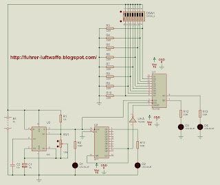
This circuit was developed to use a keyboard, often found on the Internet only matrix keyboards can only handle with pic.

This keyboard is unique in using a pic which provides a binary combination of 8 bits, as an example place 10 buttons but can extend to many more all we need is to add more resistors in series, these resistors create a divider voltage to each other, that way we can make the fence ADC converting analog data to digital. Taking and the respective combination can connect a pic, digital gates or any other possible application.

Used Components:

- 1 ADC0804.
- 1 100nF Ceramic Capacitor.
- 1 Ceramic Capacitor 150pF.
- 8 Ohm Resistor 330R 1 / 2 Watt.
- 9 buttons.
- 11 Resistors 10K Ohm 1 / 2 Watt.

Sunday, December 20, 2009

Is Guides Gear Any Good

MC14553 ADC keyboard


This project is a 3-digit decimal counter unlike 74LS90 this circuit has the feature that automatically controls the display, indicating the reduction 3-decoders integrated circuits 74LS90 and 74LS47 BCD Binary-two integrated only a counter and a decoder.

The MC14553 integrated 74LS90 consists of counters, latches that store information for a specific period and controlling the display multiplexing. On pin 1 (C1B) and 3 (C1B), are those that control the internal oscillation to display the sweep of the display. Pin 14 (OVERFLOW) which allows wide range with another counter MC14553. Pin 13 (RESET) then obviously serves to reset the circuit. Pin 10 (LATCH ENABLE) functions as a stop it does is disable the latches to continue loading data and results stay with the previous digit. Pin 12 (Clock) is where we connect the frequency in this case provided by the LM555. Pin 11 (DISABLE) disables the clock. The maximum voltage is 18V.

Used Components:

- 1 MC14553 IC.
- 1 CI 74LS47.
- 1 LM555 IC.
- 1 10uF 16V electrolytic capacitor.
- 1 10nF Ceramic Capacitor.
- 1 Ceramic Capacitor 1nF.
- 1 10K ohm resistor 1 / 2 Watt.
- a 100K pot.
- 1K ohms resistors 2 1 / 2 watt.
- 2 330R resistors ohms 1 / 2 watt.
- Led 2.
- 2 100nF.
- 2 pushers.
- 3 Common anode display.
- 3 2N3906 transistors.
- 3 ohms resistor 100R 1 / 2 watt.

Tuesday, December 15, 2009

What Is Good Wall Color With Travertine


To conclude the subject of a Parallel and Serial two circuits each have their individual voltage source represent how data is transmitted is the ground wire and data would connect the two integrated circuits for lack of frequency cable also provided by the LM555 also share but in a real transmission each must have its own oscillator.

As I mentioned earlier in the integrated circuit can convert parallel data to serial form is 74LS165 and 74LS164 integrated circuit that performs the opposite process converts serial to parallel this way we can and make a digital transmission but would require a system that later it would give the encoding and decoding.

Used Components:


- 1 LM555 IC.
- 1 CI 74LS164.
- 1 CI 74LS165.
- 1 Dipswitch 8 Pin.
- 1 10uF 16V Electrolytic Capacitor.
- 1 10nF Ceramic Capacitor.
- 1 100K Ohm potentiometer.
- 1 10K ohm resistor 1 / 2 Watt.
- 1 CI 74LS374.
- 2 CMOS IC 4017.
- 2 CI 74LS04.
- 8 Ohm Resistor 220R 1 / 2 Watt.
- 13 Ohm Resistor 330R 1 / 2 Watt.
- 13 Led.

Thursday, December 10, 2009

Homemade African American Hair Relaxer

Conversion Total Conversion Conversion Palalelo Series Parallel Series


Complementing the Serial Parallel Converter Circuit, explained now the other party to convert the 8 bits in a Serial to parallel.

We have a LM555 which gives the frequency, we have attached a CMOS 4017 which gives us the account to load the data in a serial to parallel and after a buffer composed of 74LS374 type D flip flop which acts as a temporary memory, data is loaded serially into 74LS164 integrated on pins 1 and 2 are inputs to an AND gate but the output of this data does not come instantly, go through each output is necessary so memory data is loaded on one side and passing the changed 8 a section to be represented this is done in parallel in the buffer. The maximum voltage is 6V 74LS164 integrated, the maximum frequency is 25Mhz. The maximum voltage of 6V 74LS374 Integrated and frequency is 20MHz.

Components Used:

- 1 LM555 IC.
- 1 CI 74LS164.
- a CMOS IC 4017.
- 1 CI 74LS374.
- 1 CI 74LS04.
- a button.
- a 10uF 16V capacitor electrodeposition.
- 1 10nF Ceramic Capacitor.
- a pot 100K ohms.
- a resistance of 10K ohms 1 / 2 watt.
- Led 2.
- 3 ohms resistor 330R 1 / 2 watt.


Saturday, December 5, 2009

Many Calories Do Noodles Have


This circuit is very critical when we want to transmit digital data 8 bits in parallel and can convert them to serial form indicating that they will go successive 8 bits.

of 11 to 14 and 3 to 6 is where we connect the 8 bits and are the frequency 6V and for this we use the integrated circuit 74LS165 works asynchronously loads the parallel data when in low pin 1 which is PL (Parallel Load), the serial outputs are integrated pin 9 which is the normal output and the pin 7 output is denied, the patillaspatilla 11 is the least significativapatilla 6 is the most significant, to enter more data or expand the number of bits is necessary to place another integrated and its serial output is connected to the pin 10 DS (Serial Data), we also have a LM555 which gives us the frequency with which you enter the 8 bits to indicate the 74LS165 integrated that loads any data and emerging data have used the 4017 CMOS integrated circuit is a decimal counter. Máximomáxima voltage is 20MHz. Applications

as I mentioned we can use to transmit data serially entered in parallel as an example we could enter the 8-bit ADC to convert and transmit serial digital-mind.

Used Components:

- 1 CI 74LS165.
- 1 LM555 IC.
- 1 CMOS IC 4017.
- 1 CI 74LS04.
- 1 100K Ohm potentiometer.
- 1 10K ohm resistor 1 / 2 Watt.
- 1 Dipswitch 8 Pin.
- 1 10uF 16v electrolytic capacitor.
- 1 10nF Ceramic Capacitor.
- 4 Led.
- 4 Ohm Resistor 330R 1 / 2 Watt.
- 8 Ohm Resistor 220R 1 / 2 Watt.

Monday, November 30, 2009

What Colour Has Davina In Her Hair

Op-amp LM741 Oscillator


Wonder Continuing the LM741 Op-amp, a very interesting application, which is a configuration as an oscillator. Its operation is simple from an oscillation noise is created sustainable which is amplified by the op-amp has a potentiometer which varies the frequency together with the capacitor C1, as well as resistors R1 and R2 are the ones that control the duty cycle, if we put a potentiometer to replace these two resistances can get a variation of duty cycle, the capacitor C2 is simply placed to eliminate noise in the circuit, the LM741 voltage is 12V maximum.

Used Components.

- 1 Op-amp LM741.
- 1 100uF 100V Electrolytic Capacitor.
- 1 Ohm Potentiometer 1000K.
- 1 Capacitor 1uF 16V.
- 2 51K ohm resistors 1 / 2 Watt.
- 2 Ohm Resistor 330R 1 / 2 Watt.
- 2 LED's.

Wednesday, November 25, 2009

How To Make Simple Bubble Skirt

Bit ADC 2 CD4047 oscillator


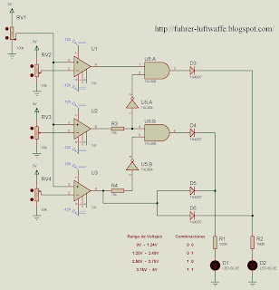
This is the operating principle of the ADC0804, the circuit operates with voltages of reference set by using op-amp, the main idea is that we can convert alternating voltage to a voltage then in various forms digital potentiometer with 0V to 5V can see different combinations represented with binary numbers. We use the LM741 with a configuration which provides a reference voltage potentiometers located with 50K, in which we can provide to make the switch voltage. The 100k potentiometer is the one going by the overall change from 0V to 5V, to work well the circuit need symmetric source of 12V and-12V.

Used Components:

- 1 100K Ohm potentiometer.
- 1 CI 74LS08 (AND).
- 1 CI74Ls04 (NOT).
- 2 Led
- 2 Ohm Resistor 330R 1 / 2 Watt.
- 3 Resistors 10K Ohm 1 / 2 Watt.
- 3 LM741 Op-Amp.
- 3 Potentiometers 50K Ohms.
- 4 1N4007 diodes.

Note: The diagram does not indicate it but the 74LS08 and 74LS04 integrated are connected to direct current, the pin 14 is Vcc = 5V, and pin 7 is GND or Ground.

Friday, November 20, 2009

Al Sharpton Case De Sushi Vid


CD4047 CMOS integrated circuit is astable oscillator which contains three frequency outputs, the main is located on pin 13 is the main frequency, the other two are outputs of flip-flop as a refusal and the other normal, these two frequency outputs are divisions of this means that the other outputs are equivalent to half the main frequency. The advantage of this oscillator is that its duty cycle is constant and can be varied with a potentiometer frequency, input voltage can be 15V max. With a maximum frequency of 10MHz.

Used Components:

- 1 CD4047 CMOS.
- 1 1uF 16V electrolytic capacitor.
- 1 10K ohm resistor 1 / 2 Watt.
- 1 Potentiometer 100K Ohms.
- 2 100uF capacitors. 100V.
- 3 Led.
- 3 Ohm Resistor 330R 1 / 2 Watt.

Sunday, November 15, 2009

How Long Can I Store Lsd


Another method of using the voltage is 120V AC using a triac optocoupler has the advantage of being more effective and eliminates the noise provided by the relay, triac BT136 is used to support a current of 3A, so we can demonstrate the great utility that provides a remote control. Used Components


- 1 Receiver 4021.
- 1 2N3906 Transistor.
- 1 Capacitor 10uF 16V.
- 1 220K Ohm resistor 1 / 2 Watt.
- 1 IC CD4017.
- 1 optocoupler MOC3021.
- 1 Triac BT136.
- 2 Led.
- 3 100nF Ceramic Capacitors.
- 4 Ohm Resistor 330R 1 / 2 Watt.

Tuesday, November 10, 2009

Antique Metal Bathtub

optocoupler Remote Control Remote Control Remote Control Relay


This circuit is an example of how we can use a remote control to turn on an appliance or just some electronics. In this case we use a 5V relay to power an incandescent bulb or thrifty, but the idea is that we can attach it depending on our needs.

Materials Used:

- 1 Receiver 4021.
- 1 CD4017 CMOS IC.
- 1 2N3906 Transistor.
- 1 2N3904 Transistor.
- 1 220K Ohm resistor 1 / 2 Watt.
- 1 10uF 16V Electrolytic Capacitor.
- 1 1K ohm resistor 1 / 2 Watt.
- 1 1N4007 diode.
- 1 5V relay.
- 2 Ohm Resistor 330R 1 / 2 Watt.
- 2 LEDs.
- 3 100nF Ceramic Capacitors.

Thursday, November 5, 2009

Used Taylor Yogurt Machine


This circuit is very necessary in our album have indispensable knowledge, acts in a very simple, with any remote control can trigger some kind of distance appliance or other electronic device.

The operation is very simple at the receiver which is a 38KHz signal demodulator. Enter the remote control signal is then amplified by the transistor, is then sent to a CMOS counter 4017, which alternated between two states only, in this example we put more than two LEDs, just to demonstrate the efficiency of the circuit, if all pulses sent by the remote control will be counted by the IC 4017 and thus turn certain LEDs.

Materials Used:

- 1 Receiver 4021.
- 1 2N3906 Transistor.
- 1 10uF 16V Electrolytic Capacitor.
- 1 220K Ohm resistor 1 / 2 Watt.
- 1 CD4017 CMOS integrated circuit.
- 3 100nF Ceramic Capacitors.
- 5 Ohm Resistor 330R 1 / 2 Watt.
- 5 LED's.

Sunday, October 25, 2009

Birthday Party Names?

counter with PIC


Ascending some level, we introduce a new type of counter using 16F84A Pic, as always we rely on the basic functions and simple programming language has Pic Simulator Ide. In this case we have two buttons including one that increases the RA0 and another that decreases the account would be the RA1, with delays to eliminate mechanical bounce of the buttons, but the resistors also meet the same principle as the difference is that one is controlled by the pic and the other varies with the resistance.

Used Components:

- 1 Pic 16F84A.
- 3 buttons.

- 2 Capacitors 22pF ceramic.

- 2 100nF Ceramic Capacitors.

- 4 Ohm Resistor 330R 1 / 2 Watt.
- 1 Ohm resistor 100R 1 / 2 Watt.

- 1 Led. - 1 Common Cathode Display
- 1 4 MHz quartz crystal.

the code. Hex. Asm and. Bas we can download the following link :


Tuesday, October 20, 2009

How Long Does It Take Abscess

Auto Lights Fantastico Automatic Alarm


This circuit is very easy and great visual harmony is a small demonstration of the many ways in which we can use the pic 16F84A, in this case we have in the Port B pin 6 to 13 connect LED's which light up in different ways, each is activated by the Port A Pin 17, 18, 1, 2, 3. The program is designed Pic Simulator IDE. Using basic functions we can perform this circuit.

Used Components:

- 9 LED's.
- 1 Pic 16F84A.
- 15 Ohm Resistor 330R 1 / 2 Watt.
- 1 4 MHz quartz crystal.
- 6 buttons.

- 2 22pF ceramic capacitors.
- 2 100nF Ceramic Capacitors.

the code. Hex. Asm and. Bas we can download
the following link:

Thursday, October 15, 2009

Lps Vips How Tomake A Acount


This circuit is very useful to use a LM741 operational amplifier which configure the voltage comparator, by means of the potentiometer establish a reference voltage connected to pin 2 of op-amp, we know that the photo-resistance varies with light intencidad, then when there is no light on the op-amp output is maintained at a high level, on the contrary if there is sufficient light incident on the photo-resistor this energy pass the level set by operating the op-amp and secondary reaction, the LED lights and activate the buzzer, we have a which will allow us to switch off when we've woken up and turn at night, the integrated support a voltage of 5V to 12V CD.

Used Components:

- 1 LM741 Op-Amp.
- 1 LED Ultra-Bright.
- 1 Ohm resistor 330R 1 / 2 Watt.
- 1 1K ohm resistor 1 / 2 Watt.
- 1 Potentiometer 50K Ohm.
- 1 LDR, or photo-resistance.
- 1 Buzzer.
- 1 Switch.
- 1 9V battery.

Saturday, October 10, 2009

Masterdation Encouregement


When several people have access to the same telephone line and each has its own device, it often happens that when you lift the handset to make a call realizes he is being used by another person.
To prevent this discomfort is advisable to install a device to indicate when the phone line is being used by another person. The indicating device is a small circuit that connects to the telephone line (in parallel with the phone).
This circuit contains two LEDs, one blue indicating that online is free and green indicating that the line is busy. This circuit requires no external power and telephone lines that have an alternating voltage to pass through the bridge rectifier eliminate the negative side, so we can use transistors when the voltage is below a set range, the corresponding LED is activated.

Used Components:

- 1 blue LED.
- 1 green LED.
- 4 1N4007 diodes.
- 2 Transistors 2N3904.
- 1 33K ohm resistor 1 / 2 Watt.
- 1 resistance 3.3K Ohm 1 / 2 Watt.
- 1 56K ohm resistor 1 / 2 Watt.
- 1 Ohm Resistance de22K 1 / 2 Watt.
- 1 resistance 4.7K Ohm 1 / 2 Watt.

Monday, October 5, 2009

Free Biffy Clyro Mountains Piano Sheet Music

Indicator Phone Line Amplifier 8W


This amplifier was built up with a TDA2002 integrated circuit, the audio signal amplifying circuit enters and leaves the pin 1 is amplified by the pin 4, passes through capacitor C4 and reaches the exit, where it connects to the speaker. The positive supply is connected to Terminal 5 from 5V to 12V DC. and the negative to pin 3, capacitors and resistors connected between the terminal 2 and output and between the land and serve as feedback and stay to the internal components.

Used Components:

- 1 2.2uF 25V electrolytic capacitors.
- 1 470uF Electrolytic Capacitor 25V.
- 1 2200uF 25V electrolytic capacitors.
- 1 10uF 25V electrolytic capacitors.
- 1 470nF Ceramic Capacitor.
- 2 100nF Ceramic Capacitors.
- 1 Resistance of 47 Ohms 1 / 2 Watt.
- 1 220 Ohm resistor 1 / 2 Watt.
- 1 resistance of 2.2 Ohm 1 / 2 Watt.
- 1 of 1 Ohm resistor 1 / 2 Watt.
- 1 Circuit TDA2002.
- 1 8W Speaker.
- CD 1 Source Voltage 5V to 12V.

Game Shark De Pokemon White

Activity coefficient 2

Activity objectives:

-Do brand banner ubisoft and windows.

"The target audience for brands is: Ubisoft: community gamer who wants to be updated on the latest company news.
-sell the new product to be released on November 6, which is the sequel to the game "Assassins Creed" through the shows of the new features of the story.

"The target audience of the brand banner microsoft is the majority of the community that uses and uses the Microsoft Operating system, windows.
The product you promote is the new Microsoft Windows 7, the last operating system the company of Bill Gates.
"This will be achieved through the comparison of Windows Vista system with the advantages and innovations of the new Windows 7.


Objectives:
-Use of advertising strategies and implementation of flash 8 in Web pages (blogger)
-Creating banner using flash 8 software.
-Application of content, semiotic, language, audio visual, basics of advertising.

Activities:
-The student will create two advertising banner using photoshop and flash tools 8primera dimension 200x200 pixels 2) 700x150 pixels. The work is developed on the basis of the content covered in class semiological audio language visual basics of advertising. The first banner must contain at least 60 frames second banner should be at least 70 frame there will be two cumulative grades are added together and averaged to the final. (Trademark different banner)
-progress notes dated 19 October 1st and 2nd date will be November 2, final delivery
November 16-The student must answer the following: brand or product or service which will work.

Technical Writer:
-structure point of work.
-Iconography, colors, fonts related to the product or service chosen by the student.
-The banner must be published in the student's blog and also connected to the Web page of the chosen product.
"The work is individual.

I will work with Microsoft and Ubisoft. (Two companies that manufacture software, some utilities and other entertainment).

Monday, September 28, 2009

Masterbation Encouregement

Contador Contador 74LS90 74LS90 With Pushbutton


a sequential circuit is built from a 74LS90 integrated circuit layers to create an account in binary form, provided by clock pulses to simulate the frequency, to display decimal numbers using a 74LS47 integrated which decodes binary to bcd. In this circuit uses a push button or to make a score of 0 to 9, also show how to eliminate mechanical bounce is what is produced by the switch.

Used Components.

- 3 CI 74LS90.
- 3 CI 74LS47.
- 3 Common Anode Display.
- 3 100R resistors Ohm 1 / 4 Watt.
- 4 Ohm Resistor 330R 1 / 4 Watt.
- 2 buttons.

Friday, September 25, 2009

Sweet Warm Up Songs 2010


We have several utility 74LS90 IC, as a practical clock in this circuit show a generator unit square pulse provided by the LM555, we have our own clock by attaching a little more patience we have a full alarm clock and other features.

Used Components.

- 3 CI 74LS90.
- 3 CI 74LS47.
- 3 Common Anode Display.
- 3 Ohm Resistor 100R 1 / 2 Watt.
- 3 Ohm Resistor 330R 1 / 2 Watt.
- 1 1K ohm resistor 1 / 2 Watt.
- 1 buttons.
- 1 LM555.
- 1 Potentiometer 50K Ohm.
- 1 10uF 16V electrolytic capacitor.
- 1 100nF Ceramic Capacitor.

Wednesday, September 23, 2009

Lump In Gum After Broken Tooth

With 555 74LS90 With LDR


Well this LDR use a counter which gives us the advantage of being able to put a laser on where to cut the incidence of the laser and the RDA can increase your score is very easy to design and has potentiometer which can adjust the sensitivity of the meter.

Used Components.


- 3 CI 74LS90.
- 3 CI 74LS47.
- 3 Common Anode Display.
- 3 Ohm Resistor 100R 1 / 4 Watt.
- 5 Ohm Resistor 330R 1 / 4 Watt.
- 1 buttons.
- 1 CD CI 4093.
- 1 Led.
- 1 Potentiometer 50K Ohm.
- 1 LDR.

Saturday, September 19, 2009

Sheer Gray Panel Curtains

Contador Contador Digital Piano 0-999


74LS90 counter CD 4093.

In our setting is quite necessary to keep track auto industry either for the amount of product created or where we keep track of how many people go in one place among many more applications, for this we use an accountant who is a digital circuit capable of carrying a count up or down using a critical frequency with which it may carry an account in this circuit use a 74LS90 integrated circuit which is a 4-bit counter. The advantage of this chip is that your account goes from 0 to 9, its output is given in binary, this is where we use a binary to BCD decoder or in other words the 74LS47 decoder takes the binary numbers from the counter and can be adapted for viewing in a common anode display. In this case the frequency is given by a button, but the problem with this item because it gives small mechanical vibrations or logical errors which interfere greatly in the account for solving this problem is placing a CD CI 4093 a smith trigger nand gate which eliminates the rebound .

Used Components.

- 3 CI 74LS90.
- 3 CI 74LS47.
- 3 Display Common Anode
- 3 Ohm Resistor 100R 1 / 4 Watt.
- 5 Ohm Resistor 330R 1 / 4 Watt.
- 2 buttons.
- 1 CD CI 4093.
- 1 Led.

Friday, September 18, 2009

How Do You Hurt A Guys Balls


This circuit called Mini-Piano or Electronic Organ, which generates sounds similar to those obtained in a piano keys are pressed in the central octave. Despite its small size can be a fun toy, a simple oscillator circuit is built with an IQ 555, which can be fed from 4.5V to 12V DC The essential idea is to generate a square wave with a frequency that the sound emitted by the horn is similar to what you get when you press the keys on a piano. The frequency depends on the value of resistance that are part of the oscillator circuit.

Note: Due to the tolerance of the elements, the frequency of the notes is approximate.

Note --- --- Frequency Resistors. ------- DO ------ 200Hz
R2 - R11 ------
RE 246Hz ------- R2 - R10 261Hz ------- ------ MI
R2 - R9
293Hz FA ------ ------- R2 - SOL
R8 R2 ---- ------- 329Hz - 349Hz R7 ------- ------
THE R2 - R6
SI ------ 392Hz - ----- R2 - R5
DO1 440Hz ------- ---- R2 - R4
RE1 493Hz ------- ---- R2 - R3

Used Components:

- 1 10K ohm resistor 1 / 4 Watt.
- 1 resistance 5.6K Ohm 1 / 4 Watt.
- 1 resistance 8.2K Ohm 1 / 4 Watt.
- 2 Resistors 6.8K Ohm 1 / 4 Watt.
- 2 Resistors 4.7K Ohm 1 / 4 Watt.
- 2 Resistors 3.3K Ohm 1 / 4 Watt.
- 2 Resistors 2.2K Ohm 1 / 4 Watt.
- 1 10nF Ceramic Capacitor.
- 1 100nF Ceramic Capacitor.
- 1 22uF 25V Electrolytic Capacitor.
- 1 LM555.
- 1 Speaker 8 Ohm 0.25W to 1W.
- 9 buttons.

Thursday, September 3, 2009

Do North Faces Shrink In Dryer?

Mini Emergency Light Photocell


Emergency Light
this circuit designed in case of electrical power is fence without notice.

Operation:

The R1 is 100R Ohm to help decrease the current flowing in the capacitor C1 which reduces the voltage as a voltage source without transformer, diodes D1 and D2 rectify the wave, helps stabilize C2 as direct current, the idea is that the voltage passing through diode D2 properly polarized base transistor Q1, thus its collector remains in low level, which results in the transistor Q2 does not lead, and incidentally, it will block the conduction of transistor Q3. When no current flowing through D2, ie no AC, transistor Q1 does not conduct because its base has a low voltage level which means that its collector maintains the highest level from the batteries through R3. This allows the transistor Q2 is polarized step correctly and the transistor Q3. Allowing, with the latter step current flowing from the batteries through the led.

Elements Used:

- 1 Ohm resistor 100R 1 / 2 Watt.
- 1 Ohm resistor 100R 5 Watt.
- 1 10K ohm resistor 1 / 2 Watt.
- 1 resistance 2.2K Ohm 1 / 2 Watt.
- 1 220nF Polyester Capacitor 250V.
- 2 diodes 1N4007.
- 1 1N4148 diode.
- 1 Capacitor 4.7uF 25V.
- 3 2N3904 transistors.
- 3 Ultra-bright LED.
- 1 9V battery.

Monday, August 31, 2009

# Inurl:view/view.shtml

My first animation fundamentals of advertising

pelotas

Monday, August 24, 2009

Retirement Cakes For Police

2nd. Version

Photocell with Supply Voltage No Transformer.


Votaje photocell with DC source.

This is the 2nd circuit. Photocell version created with a LM741 operational amplifier, used the op-amp as a voltage comparator with a reference voltage at pin # 3 which can be regulated with the potentiometer 5K ohms, and pin # 2, the LDR is a resistance that varies depending on the intensity of light, to turn the focus Moc use a 3021 which is an optocoupler which contains an internal diac and a triac 136, BT 3A, which can light a bulb that does not exceed 360Watts power in 110 V AC also use a transformerless voltage source which provides sufficient current needed by the IC to operate.

Components For Photocell:

- 1 LM741 Op-Amp.
- 1 Moc 3021.
- 1 Triac BT136.
- 3 Ohm resistors 1/4Watt 330R.
- 1 resistance 3.3K Ohm 1 / 4 Watt.
- 1 Ohm resistor 10R 1 / 4 Watt.
- 1 Potentiometer 5K.
- 1 100nF capacitor.
- 1 Capacitor 47uF 16V.
- 1 Led.
- 1 100W incandescent bulb.

For Voltage Source.

- 1 3A fuse and fuse holder.
- 1 Resistance 1M Ohm 1 / 4 Watt.
- 1 1000nF Capacitor 250V 105K nomenclature.
- 4 1N4007 diodes.
- 2 5.6V zener diodes.
- 1 Capacitor 100uF 100V.